Blog

June 18, 2012

Synthetic fat

2012-06-synthetic-fat.jpg


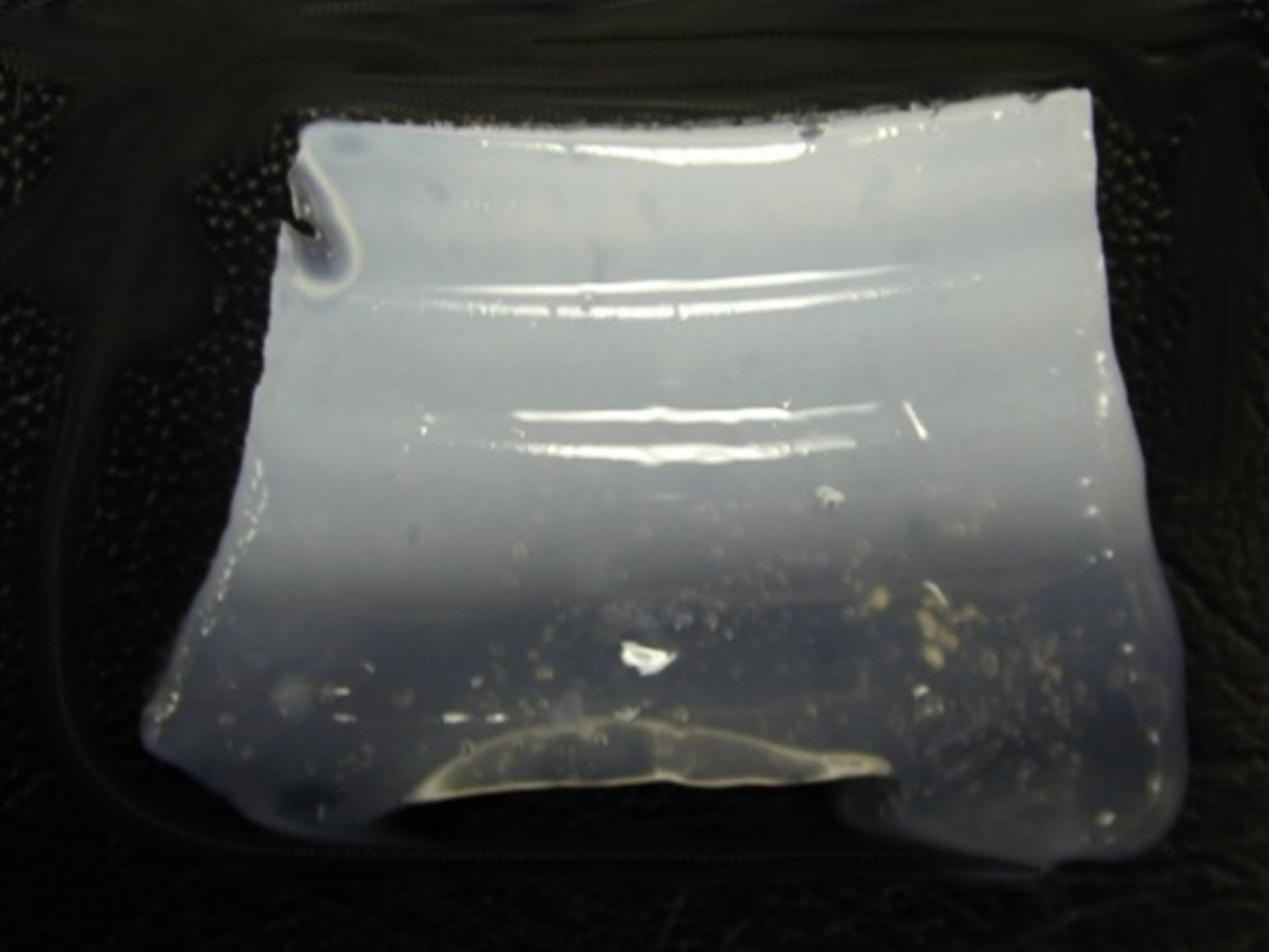
Medical device and instrumentation design and development usually requires testing the prototypes in a simulated environment. Interest in treatments involving patients with high fat content has led to requests for tissue models containing a large amount of simulated fat. Using their skills in custom polymer formulations, researchers at Cambridge Polymer Group have developed a simulated fat model for instrument testing and training. The fat model has a realistic feel, will not degrade, and can be prepared in a variety of shapes and thicknesses. Contact Cambridge Polymer Group for more details.

Posted by admin
0 Comments
May 30, 2012

UHMWPE for Total Joint Arthroplasty

2012-05-uhmwpe-for-total-joint-arthroplasty.jpg


In the 10th Anniversary Issue of BoneZone, a trade journal focusing on arthroplasty, CPG staff were asked to write an article on the history and future of ultra high molecular weight polyethylene for use in total joint arthroplasties such as hip and knee replacements.  This article breaks down the history of UHMWPE as follows:

First generation of highly crosslinked UHMWPE
First introduced in the late 1990's, these materials were irradiation crosslinked with either gamma or electron beam radiation, with doses from 50 to 100 kGy. The post-processing on these materials either involved annealing (heating below the melting temperature) or melting (heating above the melting temperature) in an attempt to reduce the number of residual free radicals that could react with oxygen, leading to embrittlement.

Second generation of highly crosslinked UHMWPE
In response to implant design requiring improved mechanical properties, second generation crosslinked UHMWPE were introduced between 2005 to now (2012). These second generation materials did not use melting to reduce the effects of free radicals, but rather addressed free radicals through mechanical deformation, repeated annealing, or antioxidants.

Future generations of UHMWPE
It is likely that future generations of highly crosslinked UHMWPE will incorporate gradients in crosslink density, providing high crosslink on the bearing surfaces, and low crosslinking in the regions requiring high mechanical strength. Alternative antioxidants will likely be considered as well.

To see the full article, follow this link.

Posted by admin
0 Comments
May 4, 2012

Gastric fluid interactions with plastics

Green apple timeline.jpg

The environment of the upper gastrointestinal tract, including the stomach, can challenge materials placed into this environment. The pH environment can range from 1.5-2.0 prior to eating, but can spike up to pH~7 during and immediately after meals, requiring an hour or more to fall back to normal levels. Contrary to commonly held beliefs, the stomach does not continuously contain fluid, but only partially fills in anticipation of eating or drinking. The peristaltic action of the stomach grinds food against the stomach walls and itself, and enzymes act to help degrade food, along with the hydrochloric acid present in stomach acid.


Polymers sometimes find their way into the stomach environment, in the form of sutures, drug-release components, satiety treatments (e.g. balloons), and other temporary or permanent implants. Knowledge of how these materials will respond to the stomach environment will help to predict their performance. In some cases, the polymers are designed to respond to the stomach environment itself, swelling or deswelling in response to pH, salinity, temperature, or fluid content. In other cases, the polymer may degrade in response to these conditions.

Researchers at Cambridge Polymer Group have designed custom systems to simulate the stomach's environment. Using test methods with reference to ASTM D523, polymers systems are tested before and after model gastric fluid exposure to demonstrate the change in mechanical, chemical, and morphological properties.

Posted by MaryOsward
0 Comments
April 12, 2012

Sol gel measurements

Sol gel experiments are a useful technique to determine the amount of crosslinking in a polymer. In this technique, samples are weighed carefully, immersed in a specific solvent at a specific temperature, and allowed to swell for a period of time, typically 24 hours. After this immersion period, the samples are removed again and re-weighed. The sample is then dried and re-weighed. From these weight changes, the percentage of the material that is soluble  ('sol') and the crosslinked portion ('gel') can be determined. Additionally, the degree of crosslinking in the gel can be determined.

ASTM D2765 describes this technique for crosslinked polyolefins such as polyethylene. The standard calls for heating jars of xylene in an oil bath. With standard oil baths, it is very difficult to achieve a uniform temperature in both the oil bath and the sample jars within the required +/- 0.5C. Cambridge Polymer Group has modified this technique with individual heater sleeves for each jar, with isolated temperature control for each jar. With this approach, we can achieve much more precise and accurate temperature control, which results in more accurate sol/gel measurements.

2012-04-sol-gel-measurements1.jpg
CPG Sol/Gel heater sleeves and control system


2012-04-sol-gel-measurements2.jpg
CPG sol/gel temperature control station
Posted by admin
0 Comments
April 2, 2012

Fingerprint analysis via SEM

2012-04-fingerprint-analysis-via-sem.jpg
Analysis of fracture surfaces of samples is sometimes complicated by inadvertent contamination the the sample surfaces during sample preparation. Dust and other debris from the lab bench, in addition to particles generated from cutting instruments, can contaminate an otherwise clean surface. If gloves are not worn during sample preparation, finger oils and salts can be left behind. As an example, a prepared polymer surface was freshly prepared by cryofracturing the sample, so that no tooling was used. The sample was then briefly touched with a bare fingertip. The sample, when imaged under SEM, shows the crystalline structure outlined in the white rectangle shown above. The elemental composition of this crystalline material is shown below, and contains salt, chlorine, and potassium. The carbon and oxygen may be from the polymer background, and/or from finger oils transmitted with the fingerprint.
2012-04-fingerprint-analysis-via-sem2.jpg
 
Posted by admin
0 Comments
March 14, 2012

Accelerated Aging

Accelerated aging protocols are key to medical device development. For initial product design, manufacturers of medical devices would like to know how their devices will respond to an in vivo environment, for a time period that could extend to decades in the case of permanent implants. For product labeling and regulatory, the manufacturer needs to be able confidently report an acceptable shelf-life for their devices before implantation or use. Shelf-life timeframes are often 2 years, and sometimes as long as 5 or more years. Clearly, this extent of time is too long for a real time aging study at room temperature.

As a result, manufacturers turn to accelerated aging protocols. For shelf-storage, there are a few ASTM methods that are used by device manufacturers. The most popular technique is described in ASTM F1980, which uses increased temperature to accelerate the kinetics of degradation of the materials. In this method, samples are usually placed in a convection oven for a period of time in their final packaging. A relatively simple expression is used to compute the accelerated aging factor, AAF

AAF=Q10^[(Ta - Trt)/10]

where Ta is the accelerated aging temperature, Trt is room temperature, and Q10 is an aging pre-factor that depends on the material. Ideally, the Q10 parameter is determined by comparing real time testing to accelerated aging testing, picking a parameter (such as tensile strength) to monitor. By measuring this parameter at multiple times during the aging study, one can construct a relationship between this property and aging time. Determining the equivalent amount of time to reach the same change in property at the different aging temperatures allows you to calculate your AAF. Know AAF and Ta, you can now calculate Q10 for your material. The Q10 will sometimes depend on temperature, as shown in the bottom graph. This plot was generated using the variable Q10 method, whereby short term real-time aging data was extrapolated to long term values as indicated.


2012-03-accelerated-aging.jpg
Posted by admin
0 Comments
February 21, 2012

Implants in the After Life

sky.jpg
Ever wonder what happens to metal hip and knee replacements after their recipient expires? How about metal pins and screws to hold bones together? In the past, these components, often composed of expensive metals such as cobalt chrome, tantalum, and titanium, were buried with the patient. Now, a Dutch Company, OrthoMetals, has teamed up with crematoriums to recover the metal components from the ash. The recovered components are not for re-use as medical devices, but rather are melted down and used in non-medical applications, such as cars, wind turbines, and general construction materials. The company, which was started in 1997, now recycles up to 250 tons of metal a year.


Posted by CatherineCerasuolo
0 Comments